
SEISMIC MODELING OF DEEPWATER CHANNEL ELEMENTS
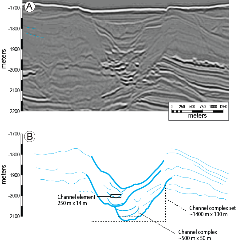
Problem Statement: Deepwater channel elements are fundamental building blocks of deepwater depositional system (Figure 1). Their internal architecture and variable stacking patterns generate variable net-to-gross distributions within channel systems and create tortuous fluid flow and connectivity pathways which impact hydrocarbon recovery.
Forward seismic modeling at the channel element scale can help to identify channel element fill and stacking pattern. The reflection character that we see in seismic is, in part, a function of the underlying stratigraphic architecture in these deepwater systems. My primary interest is to bridge the gap between architecture observed at outcrop observations and their analogous subsurface seismic responses. There has been a lot of work done in this area to qualitatively bridge this gap, but my interest is in taking it a step further to make a quantitative link.
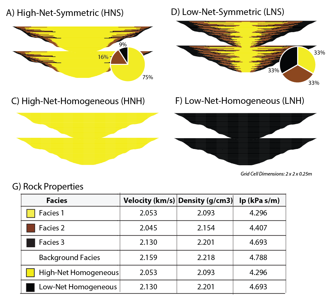
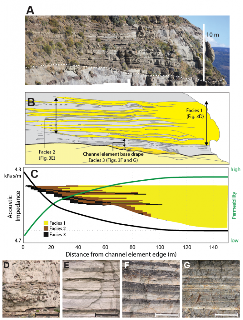
The outcrop expression of a single channel element show variations at the bed to geobody scale from thick-bedded and amalgamated sandstone to thin interbedded sandstone and mudstone (Figure 2). The rock properties assigned in this model assume low impedance sandstones and high impedance mudstone (after Stright et al., 2014; rock properties). The channel element modeled here is 250 m wide and 14 m thick.
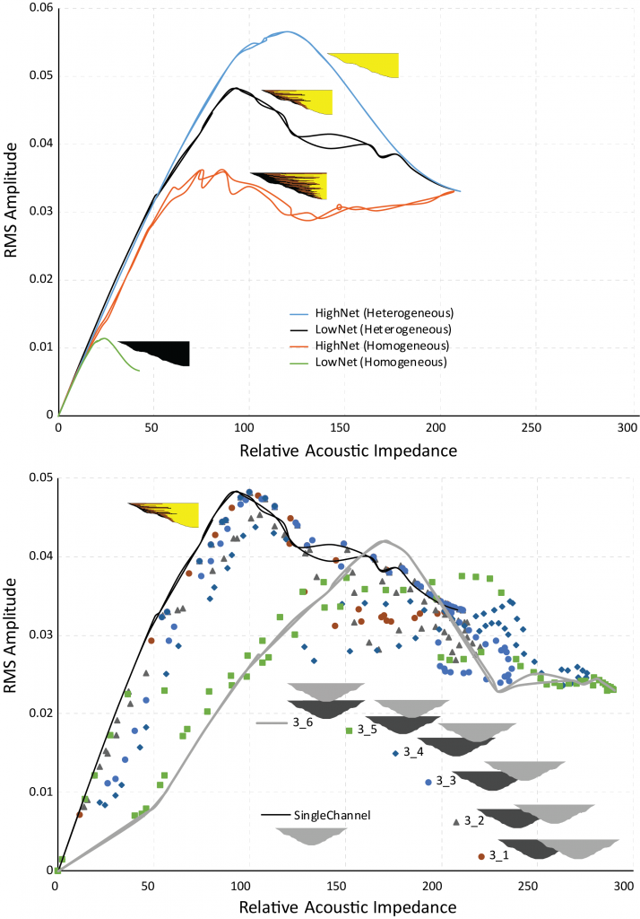
The single channel element can be treated as a wedge and the first experiment was to understand how heterogeneity in the wedge impacted the amplitude response (Figure 3). The simple single channel element models
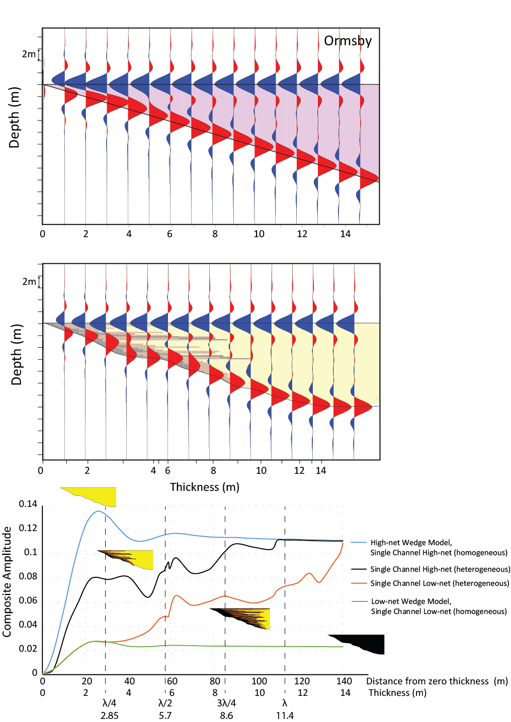
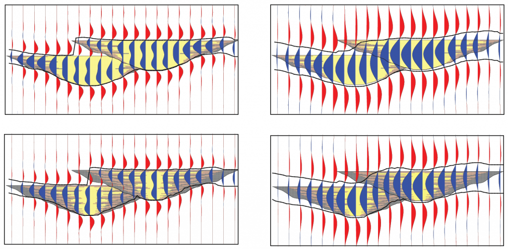
Two or more channel element models can be combines with different stacking patterns and different fills to investigate the seismic response.
Research Questions: Can these simple channel element models be used as a foundation for quantitative interpretation? The goals would be to answer:
- How many channel elements are there: 1 vs. 2 channel elements?
- How are the channel elements stacked: laterally, vertically or in between?
- What is the internal architecture of channel elements: homogeneous vs. heterogeneous, high-net vs. low net?
My hypothesis is that by comparing 1) two channel model to a single channel model, and 2) homogeneously filled models to heterogeneously filled model, we might be able to say something about stacking patterns and fill. Furthermore, we could then apply what is learned in these small template-based models to a full scale field model to test out ability to differentiate numbers of elements, stacking patterns and fill. In my mind, this is a nice small test to scale up for interpretation workflows, analyzing inversion results, and understanding what machine learning approaches are actually classifying.
Plots that we have made to try to explore patterns in the data:
- Interval attributes (RMS Amplitude) vs. apparent thickness
After the recent conversation on Sw.Ung I started playing around with sum of amplitudes from Relative Acoustic Impedance (RAI) and Cosine of Phase. - Interval attributes (RMS Amplitude) vs. true net thickness
- Cross-plots of interval attributes (e.g., RMS Amplitude vs. sum of amplitudes from RAI)
Most of these plots are so noisy, that patterns are difficult to see.
If you were tackling this problem, what might you try?
Email me at lisa dot stright at colostate dot edu
References:
Jackson, A., Stright, L., Hubbard, S.M. and Romans, B.W., 2019. Static connectivity of stacked deep-water channel elements constrained by high-resolution digital outcrop models. AAPG Bulletin, 103(12), pp.2943-2973. https://doi.org/10.1306/03061917346
McHargue, T., Pyrcz, M.J., Sullivan, M.D., Clark, J.D., Fildani, A., Romans, B.W., Covault, J.A., Levy, M., Posamentier, H.W. and Drinkwater, N.J., 2011. Architecture of turbidite channel systems on the continental slope: patterns and predictions. Marine and Petroleum Geology, 28(3), pp.728-743. https://doi.org/10.1016/j.marpetgeo.2010.07.008
Stevenson, C.J., Jackson, C.A.L., Hodgson, D.M., Hubbard, S.M. and Eggenhuisen, J.T., 2015. Deep-Water Sediment BypassDEEP-WATER SEDIMENT BYPASS. Journal of Sedimentary Research, 85(9), pp.1058-1081. https://doi.org/10.2110/jsr.2015.63
Stright, L., Stewart, J., Campion, K. and Graham, S., 2014. Geologic and seismic modeling of a coarse-grained deep-water channel reservoir analog (Black’s Beach, La Jolla, California) Seismic Modeling of a Deep-Water Reservoir Outcrop Analog, California. AAPG bulletin, 98(4), pp.695-728. https://doi.org/10.1306/09121312211